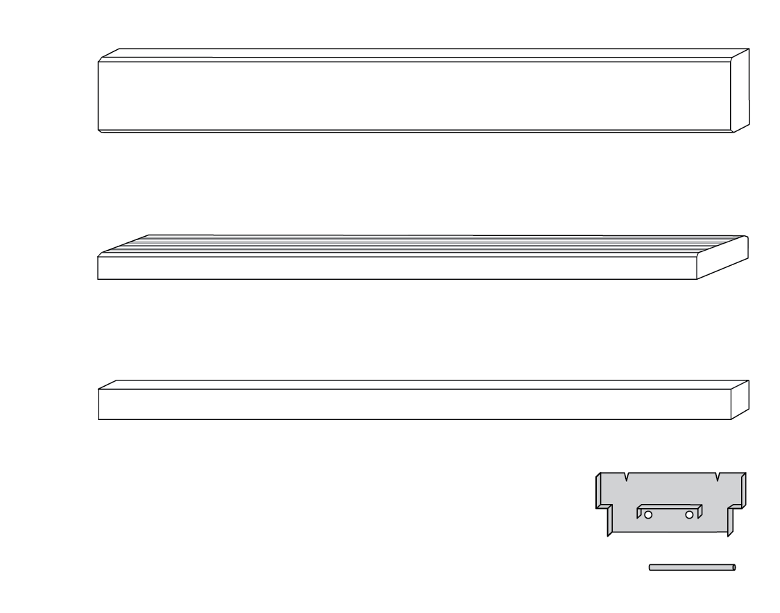
2 x Step Support Plates + 4 x Locating Pins for each layer
Note
Step Kits are not supplied with Steel Channels (sold separately).
Steel Channel lengths and type requirements will vary due to specific site conditions.
Measurements - Width
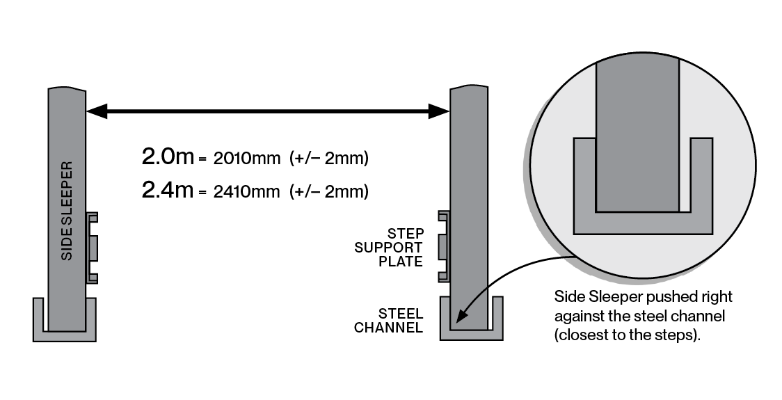
Step Tread Width / Opening Allowance
Measure from Side Sleeper to Side Sleeper.
Do not measure from the sides of the Steel Channel.
Measurements - Length
Side Sleeper Length Allowance
Measure from Side Sleeper to Side Sleeper.
Do not measure from the sides of the Steel Channel.
Step 01
Prepare the Side Sleepers
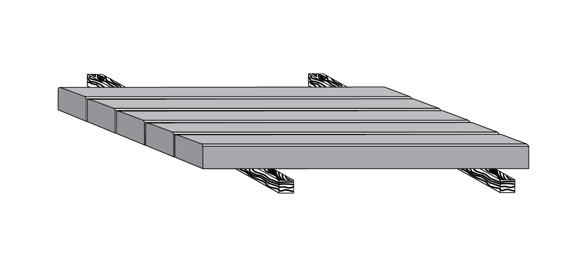
Lay two timber bearers on flat ground.
Rest the Side Sleepers face up (plain face/no pattern) on timber bearers, one for each layer.
Align the Side Sleeper ends in a row, ensuring a straight edge to work off – left-hand edge for left hand side of the stairs and right-hand edge for the right.
Step 02
Placement of Step Support Plates
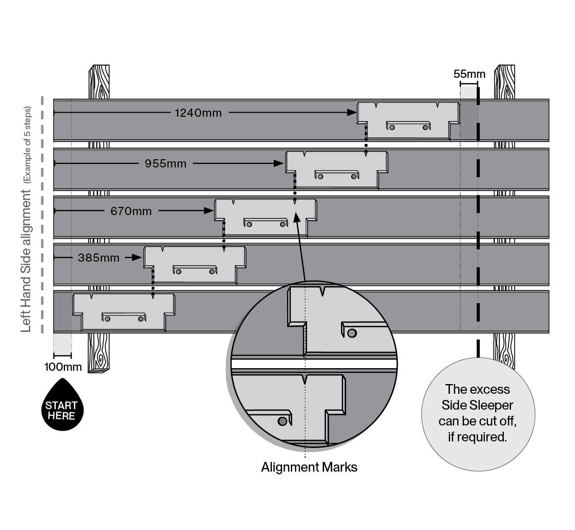
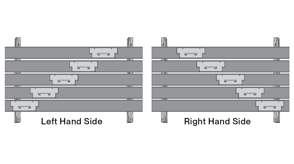
Place the first Step Support Plate centrally on the lowest sleeper, 100mm from the edge, to allow for the Channel Column.
There are two methods for fixing the subsequent Step Brackets. Choose one from below:
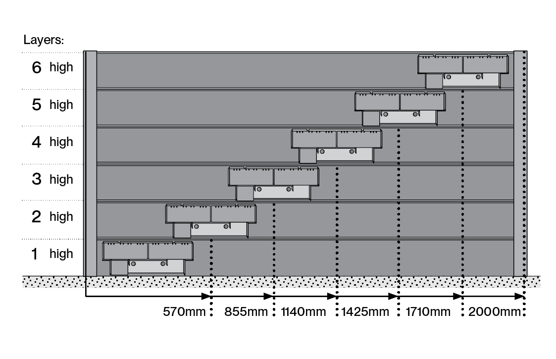
Method One: The Step Support Plate has two notches cut in the top edge. These are Alignment Markers for easy spacing with the next plate. In all cases, the front bottom edge of the higher Step Support Plate must align with the lower notch, as shown above.
OR
Method Two: Using the above diagram, measure the distance from the front edge of the Side Sleeper to that of the Step Support Plate being laid.
When aligning the Step Support Plates on the right hand side, the same procedure applies, using the opposite notches, and starting from the right hand side.
Step 03 - Part A
Drill Pilot Holes
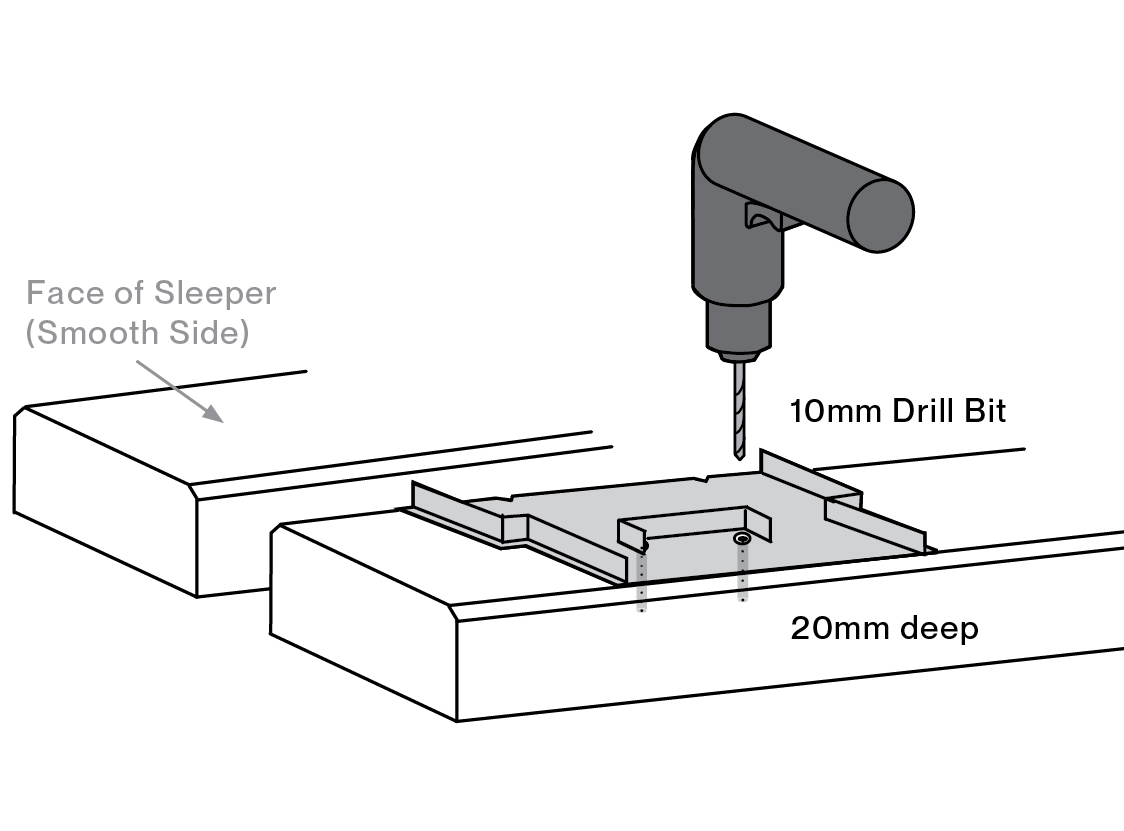
With all of the Step Support Plates now positioned, drill through the two attaching holes with a 10mm masonry bit, to a depth of approximately 20mm.
Tip #1: Ensure that the plates are held centrally on the sleeper before drilling. Tip #2: A second person may be needed to hold the plate in position whilst drilling is being done.
Step 03 - Part B
Hole Preparation
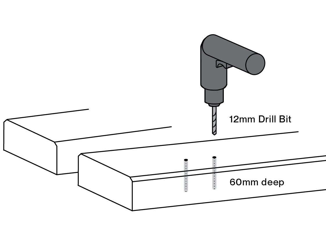
Now that all pilot holes have been drilled, remove the Step Support Plates and re-drill ALL the holes out to 12mm diameter and 60mm deep.
Tip #1: Keep the drill perpendicular to the sleeper when drilling.
Step 04 - Part A
Prepare for the Locating Pins
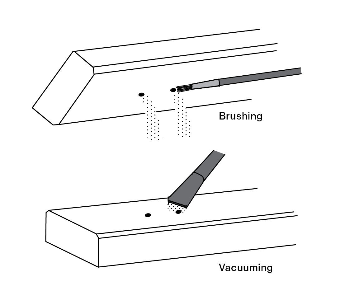
Before the Locating Pins can be inserted, the holes drilled at Step 3 must be cleaned out of any concrete dust and chips to ensure a good bond with the Chemical Anchor Glue.
This can be achieved by either:
Tilting the sleeper over and manually brushing out the dust.
Blowing the dust out with air (while wearing safety goggles).
Vacuuming the dust out.
Step 04 - Part B
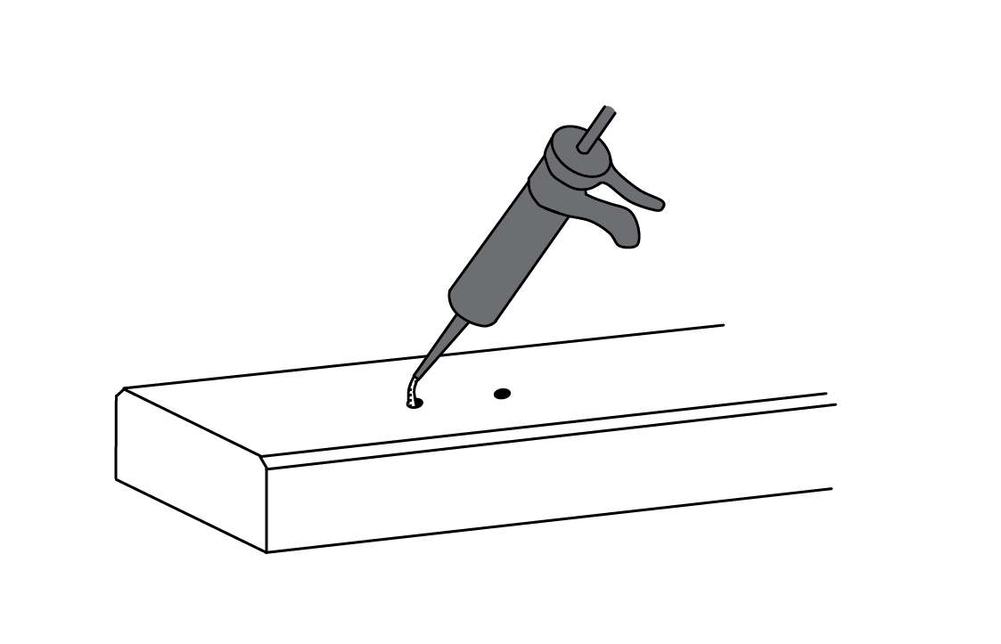
Add Chemical Anchor Glue
Using the recommended Chemical Anchor Cartridge, half-fill each hole with glue.
Step 04 - Part C
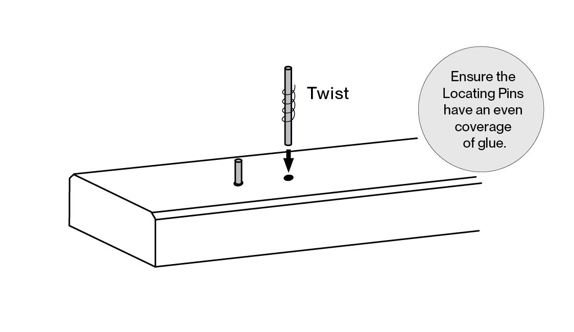
Insert Locating Pins
Within 5 minutes of application, push in the Locating Pins using a twisting motion (to eliminate air bubbles) until they are firmly seated at the base of the hole.
Wipe away any excess glue.
Tip #1: Step 5 should follow quickly.
Step 05
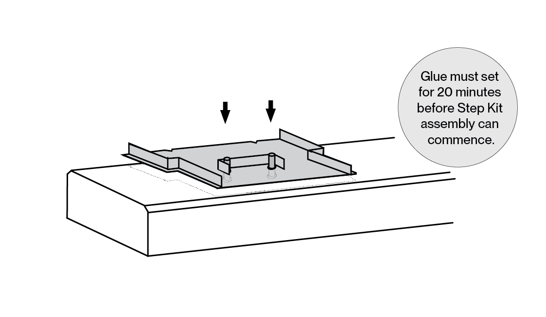
Attach the Step Support Plates
Before the Chemical Anchor Glue sets, it is advised to place the Step Support Plates over the Locating Pins to ensure a correct fit. Make sure the plate sits firmly and squarely against the Side Sleeper front face.
Continue with all the Step Support Plates for this side of the wall, but don’t fit any into the column channels yet.
Allow the Chemical Anchor Glue to cure for at least 20 minutes before Step Kit assembly.
Step 06
Repeat the Process
Steps 1 to 5 can now be repeated for the side walls, taking care to follow the alignment rules and working from the front bottom to the rear top step.
Step 07
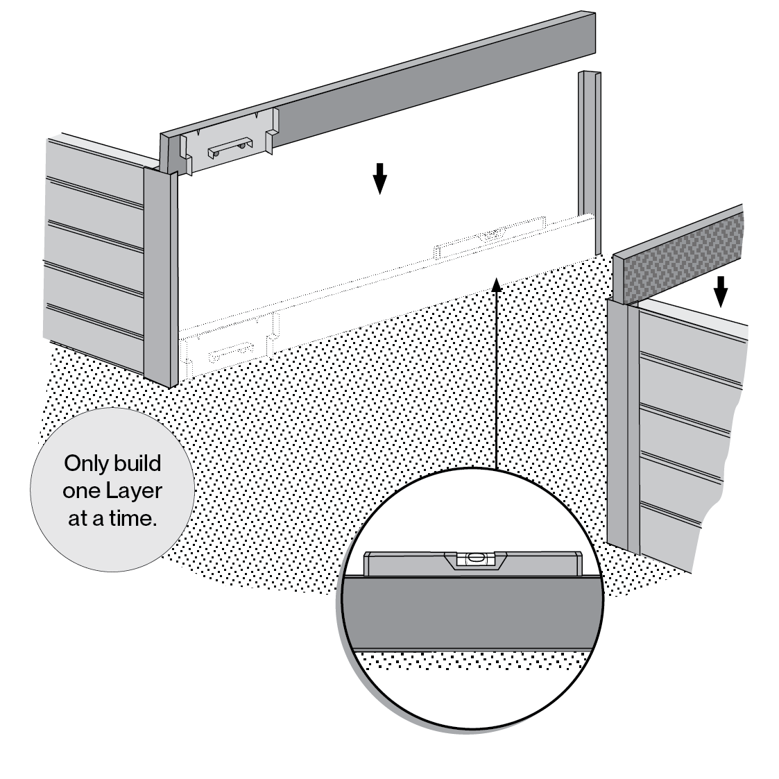
Place Side Sleepers into the Wall
Starting from the bottom, place the lowest Side Sleeper on the prepared, smooth, solid surface, between the Channel Columns.
Use a spirit level to ensure the Side Sleeper is perfectly level.
Repeat for the bottom sleeper only on the other side.
Step 08
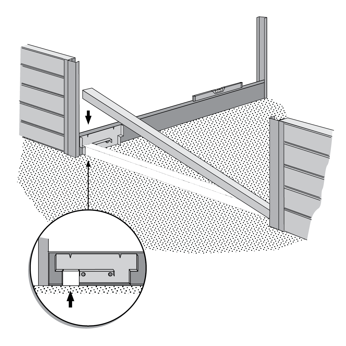
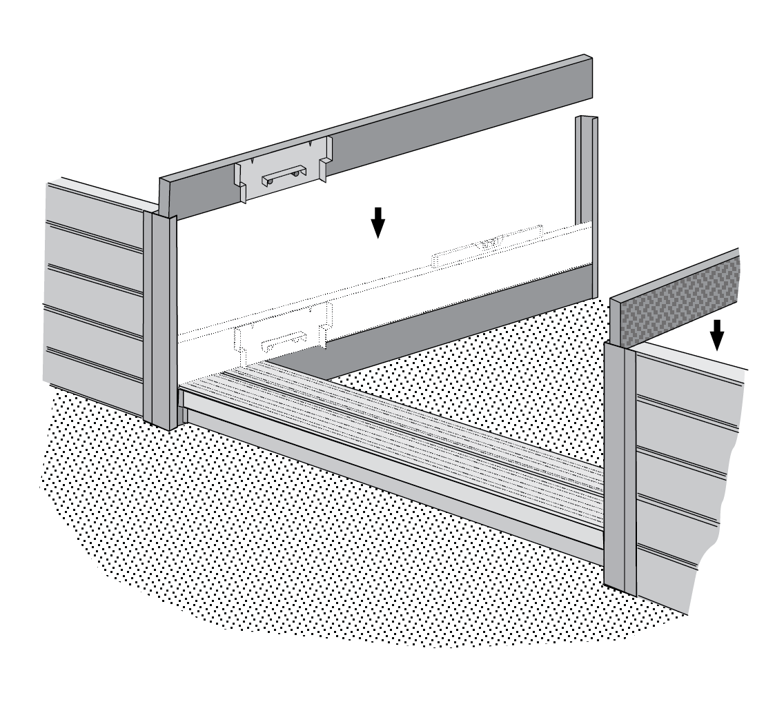
Insert Crib/Riser as shown below.
Place a Crib/Riser between the Step Support Plates in the forward-most opening.
Step 09
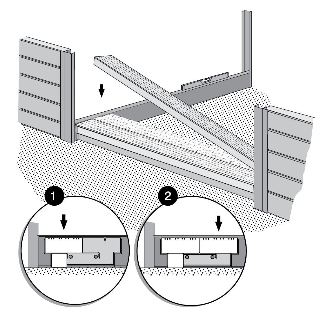
Place Step Treads onto Step Support Plate Bracket
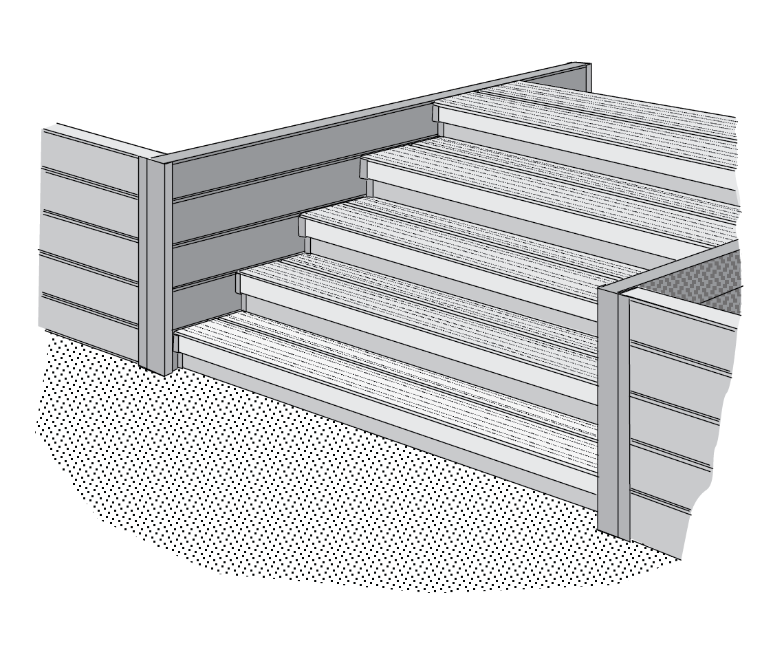
Add the first Step Tread onto the Step Support Plate bracket at the ‘front’ (covering the Crib / Riser). Add the second Step Tread behind the first, as shown above. This will complete the assembly of the lowest layer.
Backfill after each layer.
Step 10
Repeat for each Layer
Repeat Steps 7-9 for all remaining layers until the Step Kit is complete.
Tip #1: IMPORTANT Do not add the next Side Sleepers before placing the Crib/Riser and Step Tread on the existing layer.